How To Assemble The Dewar A go to guide on assembling the Dewar Cryostat for SNSPDs in GQuEST
16 Oct 2025 - 22:09
|
Version 4
|
Alex Ramirez
Assembly of the Dewar
In this guide you will find a step by step procedure on best practices for assembling the Dewar Cryostat for SNSPDs in GQuEST.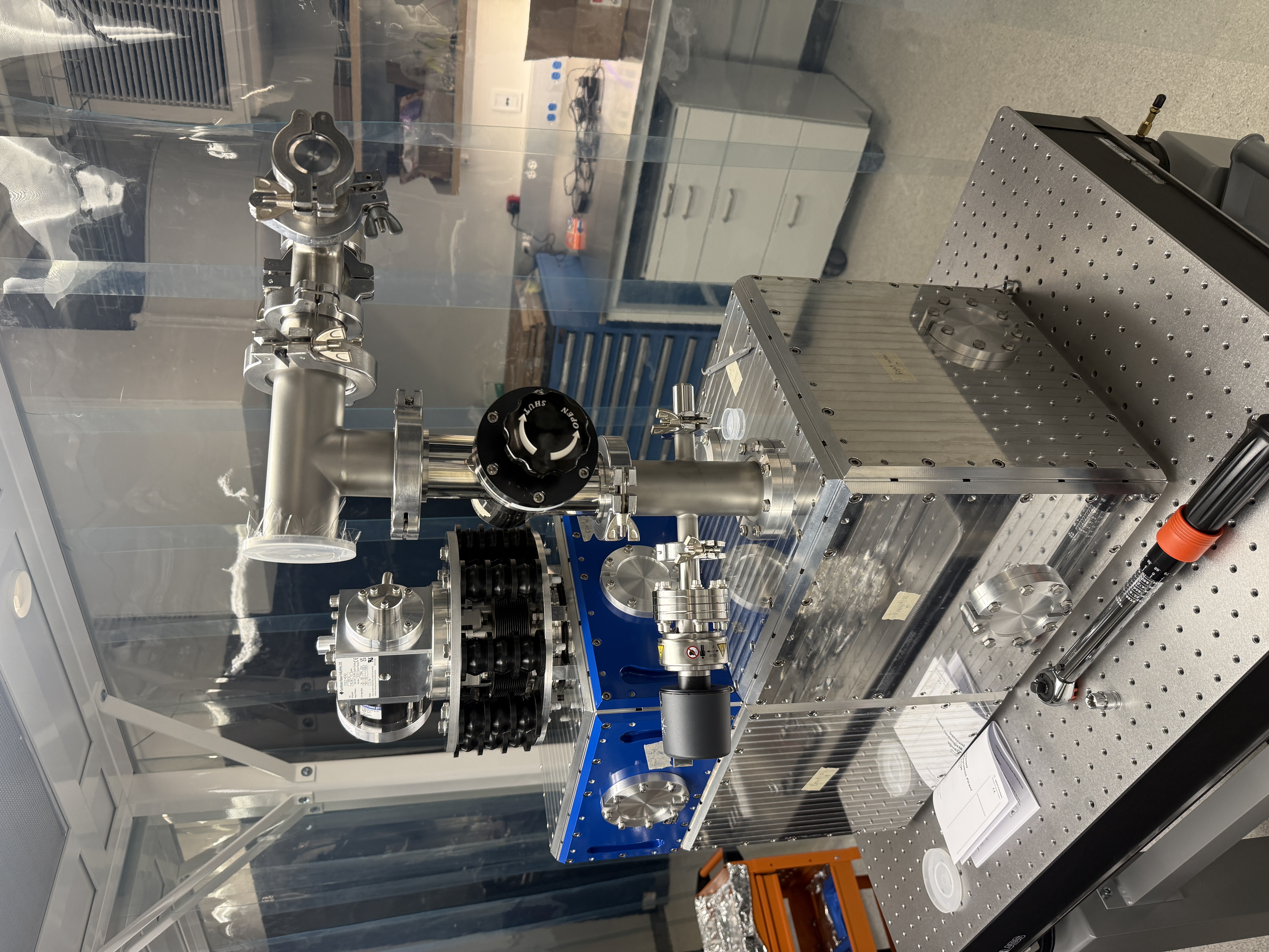
Essential Notes and Specs:
Exterior
All Ideal Vacuum bolts for the Cryostat system are rated and expected to be tightened to 70 lbs/in. (Use a torque wrench)
For consistency, the C-Clamps for feed throughs and all various other flanged attatchments are also tightened to 70 lbs/in rating.Interior
Step by step Assembly:
Exterior
Ideal Vac Plate AssemblyAssembling the exterior of the cryostat is simple. It consists of carefully placing the ideal vacuum plates onto the frame and securing them evenly using a torque wrench.
- Start with the bottom two plates of the cryostat. ensuring that when the frame is flipped upside down, you do not scratch or bump the frame in any way. Please protect the polished edges with the 3D printed covers or kapton tape.
- For each plate, remove o-ring, and clean it with a clean vacuum safe cloth and isopropyl. Also clean the interior facing side fo the plate and the o-ring groove.
- Place bottom plates on cryostat in the correct orientation: see the CAD drawings (plates should be labeled).
- The bottom ideal vac plates each have 2 pairs of holes near one edge of the plate on the inside. These holes should both me oriented on the outter edge side of the frame as they will mount the garolite stands for the copper cubes.
- Next You may assemble all the remaining plates onto the frame (leave top most plate for last), being careful to check positioning and ensure the use of proper torqueing on the bolts.
- The top most plate with the GM Cooler absorption should be the last item you bolt on, as it will take a few extra steps. There are 2 inaccessible bolts that you will need to use a low profile allen key to access and tighten manually.
- To access one of these bolts you will also need to fully remove the bolt that is directly over the hole and wiggle the threaded clasp to one side to access the hole for the plate.
- Do the reverse of step 5 to reinsert the bolt into the clasp and finish the setup.
Vacuum Pump and Valving System
A diagram is shown describing the current vacuum component system for the cryostat.
Interior
40K Cube Assembly
Assembling the interior of the cryostat takes a bit more time and patience. Be sure to always take care and precaution when screwing any bolts into copper! There are no helicoils, so if anything is stripped there may be issues.
All bolts are necessary for thermal contact. Assume all interior bolts need and or have a spring washer for them! The corresponding washers and bolts are detailed in the drawing files.
Please clean all parts and bolts with isopropyl and or high frequency sonicator before inserting inside chamber.- To begin assembly of the SNSPD cryostat interrior, first clean and lay down the 1 inch square aluminum bars (will be used as spacers) and the 1/8 in thick aluminum shim stock on top as shown in picture.
- Next, clean the copper cubes and cover all through holes on underside of the cubes are covered properly with copper tape.
- You may now carefully clean and load the 50K interrior copper cubes on top of these spacers, using them as a support system. These are used to bring the cubes to the proper height for assembling the G10 stands.
- You may also want to attatch any of the top outter aluminum shield plates at this time as well as it may be hard to reach after installing.
- Next bolt the two large 50K copper cubes together with appropriate bolts and spring washes.
- Once the cubes are in place, and all interior bolts are in, you may load the copper onto the G10 stands designated for the outter cubes.
- Be careful when screwing the G10 stands in place and be sure that the cubes are even when tightening the bolts.
- First lightly thread all bolts into the stands (without having removed the spacers yet).
- Tighten the copper facing bolts on the stands
- Remove the spacers
- Tigthen the G10 plate bolts
- Loosen the G10 bolts in the copper cubes of one stand and then tighten it down after it moves to where it wants to be. This is to ensure the stands are perfectly straight, do this process individually for each stand, one at a time.
- Be careful when screwing the G10 stands in place and be sure that the cubes are even when tightening the bolts.
- Now that cubes are suspended by the G10 rods and all rods are tightly secured, remove the supporting bars and shim carefully.
- You may proceed to secure plates and any components inside to the 40K boxes now.
- Once everything is assembled install all plates, and any covers for holes on each palte for feed throughs.
4K Cube Assembly
- To begin assembling the 4k cube, start by cleaning it and all components to be secured on it.
- to properly fit the 4K cube into the 40 K cube, you will need to assemble the 4k cube with the chase cryocooler (helium sorption pump) and aluminum can shield.
- Ensure the cable for the cryocooler is installed and the wires are easily accessible once the cube is installed!
- To actually get the 4K cube into the 40K box with the pump and can installed DO NOT PUT THE LID ON THE CAN. It will not fit.
- Use 2 people to carefully menuever and tilt the cube, cryocooler first, into the 40K box. Then once in, the can should just barely be able to tilt back up straight and the cube can rest on the bottom of the 40K box.
- Once the 4K cube is properly inside the 40K box, you may install the top of the pump radiation shield can.
- Next begin to assemble and install the electronics, detectors, and so on as outlined in next few sections.
- Finally, install the copper plates to 4K cube making sure to have a firm seal and tighten in star pattern, do not over tighten or strip the threads!!


Internal Electronics (DC)
Internal Electronics (RF)
Internal Electronics (Bias)
Ideas, requests, problems regarding Foswiki? Send feedback