1. Introduction
This document is the Standard Operating Procedure (SOP) for 145mW, 1550nm Thorlabs Turnkey Laser in West Bridge B102 (ULN15TK). This laser is used for the assembly of GQuEST related interferometers and filter cavities. The ULN15TK is a Class 1M, fiber Bragg grating (FBG) laser system with output at 1550nm, with an absolute maximum output of 145mW. Although not initially, the use of an NKT Photonics Koheras BOOSTIK HP 15W Amplifier is planned for B102. This product is a class 4 Laser system; class 4 laser systems are dangerous and has the potential to cause damage and injury.1.1 Room B102
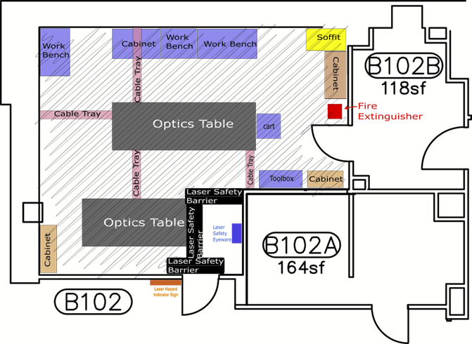
The floor plan of Room B102 is shown in Figure 1. The area indicated by hatching is the Nominal Hazard Zone. The area between the laser safety barrier and the entrance door is non-hazard area that is designated for storing and donning laser safety glasses.Figure 1. The floor plan for Room B102.
2. Hazards
2.1 Laser Radiation Hazards
The FBG laser is an infrared laser and is invisible to the naked eye. The output power of this laser alone can be operated above the accessible emission limit (AEL) of 1.9 mW and 96 mW for both eye and skin respectively. With the amplifier in use, the output can be operated at well above the AEL. Extreme caution should be taken when operating the laser with the amplifier.2.2 Electrical Hazards
The system is powered using Thorlabs’ DS12 power supply (12 V, 4 A). There are no electrical hazards when operating the laser.2.3 Fire Hazards
Operating the BOOSTIK amplifier at powers on the order of 10 W has the potential for fire. Ensure the beam is only directed at approved optics equipment or qualified beam dumps. Check Figure 1 for fire extinguisher location. Fire extinguisher #00007776.3. Hazard Controls
3.1 Access Controls
There are no active access controls to West Bridge Room B102.3.2 Beam Controls
There is a Laser Enable PushButton Switch that be used to shutter the laser. The laser will remain on at all times to increase the operating life length of the laser.3.3 Laser Interlock
The ULN15TK is equipped with a remote interlock connector located on the rear panel. In order to enable the laser, a short circuit must be applied across the terminals of the Remote Interlock connector. This connection is made available to allow the user to connect a remotely actuated switch to the connector. All units shipped from Thorlabs are configured with a shorting device installed in the interlock connector. This device can be removed, and a 2.5 mm mono jack can be installed to provide remote interlock connectivity. A safety door switch circuit is connected to the LEMO interlock connector of the BOOSTIK HP system. The door switch circuit is part of the system’s interlock circuit and connected to the BOOSTIK HP amplifier through an External bus connection from the seed laser. Refer to the ADJUSTIK or ACOUSTIK product guides for specific information on connecting a safety door switch to either device. This interlock must be CLOSED for emission to be permitted.3.4 Safety Sign
A laser hazard indicator sign is located at the outside of the room. Whenever there is a possibility to use the laser beam for a task, this sign should be turned on by a switch next to the entrance door.3.5 Laser Safety Eyewear
The use of laser safety eyewear is mandatory whenever the laser power supply is energized. A minimum optical density (OD) of +3 at 1550 nm is required. When the amplifier is introduced a minimum of OD 7+ 1550nm is required. C2KG5 laser safety goggles are stored in the entrance area. These goggles have filtering at the following wavelengths: OD 6+ @530-570nmOD 4+ @655-664nm
OD 5+ @665-679nm
OD 6+ @680-695nm
OD 7+ @696-1550nm Always double check the listed filtering on the side of the goggles before entering the laser hazard area.
3.6 Handling of the optical fiber
The laser source output is a PM, FC/APC Bulkhead optical fiber. This will initially be connected to a fiber coupler, where the max output of this fiber is 145 mW. The laser source should be turned off when handling the output fiber. This output will eventually connect to the BOOSTIK amplifier.4. Training
Users of the ULN15TK laser BOOSTIK amplifier should have received the LIGO Project’s basic laser safety training. They are not permitted to operate the laser by themselves until they have received this training.5. Operating Procedures
Items such as jewelry and watches should not be worn while manipulating beams on the optical table.
Caution should be exercised when one’s head passes through the plane of the laser beam.
Prior to turning on the laser or enabling via the Laser Enable PushButton Switch:- check the beam path to ensure that there are no reflective objects in the beam path that may unintentionally deflect the beam
- alert any personnel in the room that the laser is about to be operated and ensure that everyone is wearing the appropriate laser safety eyewear
- check that the laser warning sign is illuminated
- scan the optical table for any stray beams and correct the situation as necessary
6. Emergency Procedures
In case of an emergency, call x5000.
Ideas, requests, problems regarding Foswiki? Send feedback
This website is using cookies. More info.
That's Fine